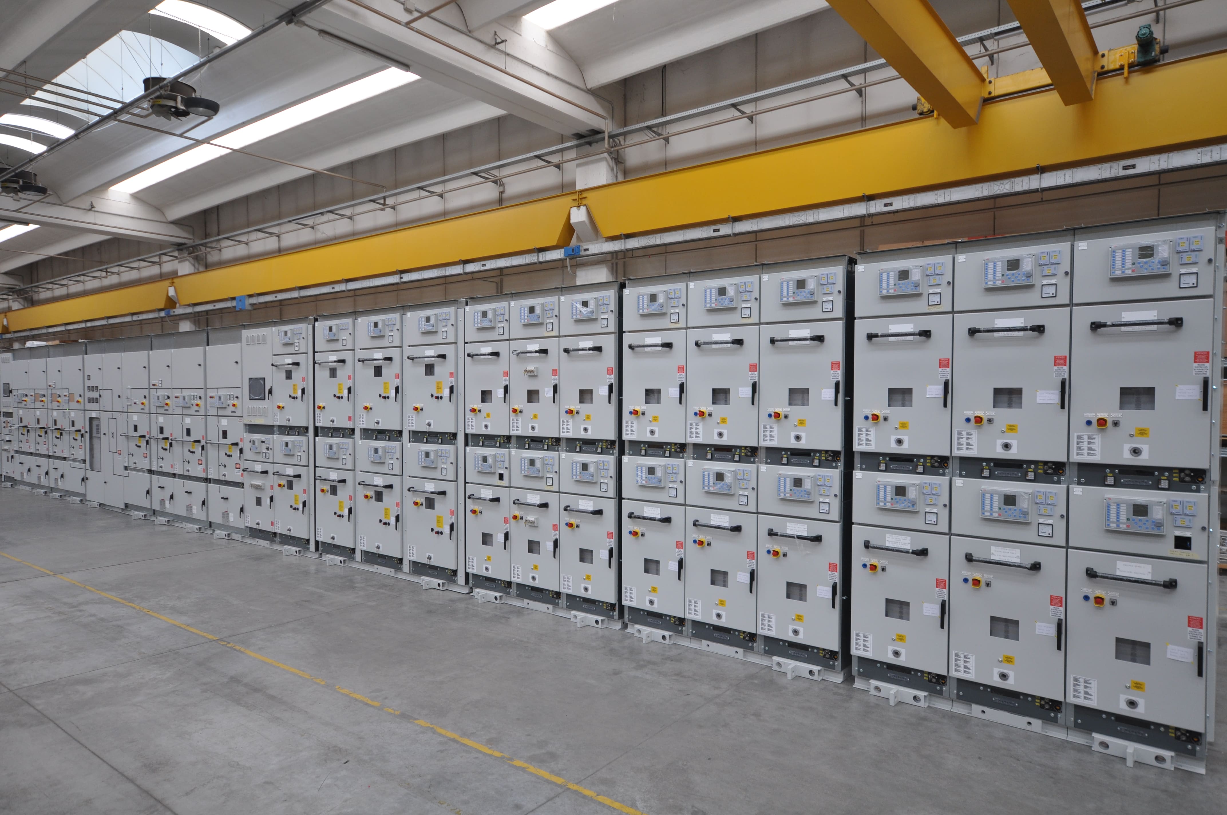

The IAC classification indicates how medium-voltage switchgear behaves in the event of an internal arc, with regard to personnel protection and under the conditions specified for the test. To understand it correctly, the type of accessibility, the sides covered by the classification, the arc current and duration, and the installation characteristics within the room must all be considered together.
The designation shown in the switchgear documentation and on its nameplate is therefore the starting point. For the declared performance to be applicable to the actual installation, the conditions specified by the manufacturer must also be met, including the room layout, distances from walls, and gas relief path configuration.
This article explores the topic of internal arcing within the scope of the IEC 62271-200 product standard.
What is an internal arc in MV switchgear?
An internal arc is an electrical discharge which, unlike a solid short circuit between live conductors or between a live conductor and earth, develops through the air inside the switchgear following a fault. It may, for example, be caused by insulation deterioration or an inadequate tightening of connections.
The energy released causes a rapid increase in temperature and pressure, generating hot gases and potentially ejecting incandescent material. These effects can pose a risk to people in the vicinity.
Switchgear design must therefore consider both fault prevention and the management of fault consequences. In any case, IAC classification concerns the switchgear’s ability to protect personnel in the event of an internal arc; it does not mean that the switchgear design guarantees that such a fault cannot occur.
What does IAC mean in IEC 62271-200?
IAC stands for Internal Arc Classification.
IEC 62271-200 is the reference standard for AC metal-enclosed switchgear and controlgear with rated voltages above 1 kV and up to and including 52 kV. Within the scope of this standard, the IAC classification identifies performance under defined conditions. At present, it is not a mandatory requirement, but it is nevertheless standardised when requested by the customer.
To describe the classification correctly, the following information must be known:
- the type of accessibility (the protected sides of the switchgear to which the classification applies);
- the rated internal arc current;
- the rated arc duration;
- the specified installation configuration and conditions.
Simply referring to IEC 62271-200 does not communicate all of this information: the IAC classification must be specified in the user’s requirements.
How is the IAC AFLR designation interpreted?
As an example, consider the designation IAC AFLR 25 kA 1 s.
| ELEMENT | MEANING |
| IAC | Internal Arc Classification |
| A | Accessibility restricted to authorised and qualified personnel |
| F | Front side tested |
| L | Lateral sides tested |
| R | Rear side tested |
| 25 kA | Maximum rated internal arc current |
| 1 s | Maximum rated internal arc duration |
The letter A concerns who is permitted to access the area. The letters F, L and R identify the sides of the switchgear covered by the performance declaration and, consequently, the areas where an operator may physically be located while remaining protected from the effects of a potential internal arc within the equipment.
Accessibility type B, on the other hand, refers to access that is not restricted to authorised personnel and may, in a broader sense, also include members of the public.
Current and duration must be considered together. Stating only “25 kA” does not fully describe the internal arc performance, since the duration has a significant effect on the amount of energy to which the equipment is subjected. A duration of “1 s” represents the maximum rated duration of the event, within which the fault is expected to be extinguished or otherwise interrupted by the electrical protection systems installed in the plant.
What is the difference between IAC AFL and IAC AFLR?
IAC AFL covers the front and lateral sides, whereas IAC AFLR also covers the rear of the switchgear.
This difference is important when designing the switchgear room. If an accessible rear corridor is provided, that side must also be taken into account when selecting the classification.
Wall-mounted arrangements must nevertheless comply with the distances and conditions specified by the manufacturer. Moving switchgear closer to a wall does not automatically make any solution valid: the layout must be consistent with the configuration subjected to the tests required by the standard.
What is verified during an internal arc test?
The test considers the effects of the arc on the switchgear and, consequently, on the surrounding accessible areas, according to criteria defined by the standard.
The aspects assessed include the behaviour of doors and covers, the ejection of parts, perforation of the enclosure, the effects of hot gases on the test indicators, and the maintenance of the earth connection.
The classification applies under the specified and documented conditions, namely during normal operation, with doors and panels closed. It must not automatically be extended to operations with doors or panels open, nor to configurations other than those permitted.
When assessing switchgear, it is also useful to verify which compartments and configurations are covered by the available test evidence.
What are gas relief systems used for in MV switchgear?
Gas relief systems are used to manage the overpressure generated by an internal arc and to direct hot gases along a path defined by the design.
Depending on the construction, the system may include pressure-relief openings, ducts, or devices designed to reduce the effects of the gases. The path may direct the discharge outdoors or use other configurations expressly permitted by the manufacturer.
The key point is to control where the gases are discharged and which areas may be affected. For this reason, the gas relief path must be assessed together with working spaces, access routes, and accessible areas.
The length of the ducts, bends, restrictions and obstacles can affect gas flow. A seemingly minor modification may alter the expected behaviour and must therefore be assessed before installation.
How does the room affect the IAC classification?
The switchgear and the room must be designed in coordination. Installation conditions may include:
- minimum clearance between the top of the switchgear and the ceiling;
- distances from walls and other obstacles;
- location of accessible corridors;
- characteristics of foundations and fixings;
- configuration of the gas relief path;
- openings and volumes required for gas discharge.
There are no universal distances that apply to all IAC-rated switchgear. The values to be complied with depend on the specific model and configuration subjected to the relevant tests.
For example, a cable tray installed above the switchgear could interfere with an upper gas relief outlet. A duct rerouted to avoid a beam could introduce conditions different from those documented. Such conflicts must be resolved during the design stage, in consultation with the manufacturer.
What is the role of electrical protection systems?
The IAC classification and the plant protection system must be assessed together.
The current and duration values declared for the switchgear should be compared with the fault conditions and the expected fault-clearing times. Reducing the arc duration can significantly limit its effects.
Depending on the design, dedicated arc detection or mitigation systems may also be considered. Their presence nevertheless requires verification of coordination with the switchgear and with the other protection systems.
An effective technical review therefore compares three elements: switchgear data, the protection study, and the room layout. These must describe mutually consistent conditions.
What should be checked before selecting IAC-rated MV switchgear?
During the specification and purchasing phase, the following aspects should be clearly defined:
- the IAC classification, including maximum current and duration;
- the sides that will be accessible in the installation;
- the operating configurations;
- the conditions required for the room;
- the gas relief path and discharge location.
This information makes different proposals comparable and helps identify at an early stage any constraints that could require modifications to the civil works.
Frequently asked questions about IAC classification
Does IAC-rated switchgear prevent an internal arc from occurring?
No. The classification describes how the switchgear behaves with regard to the effects of an internal arc under the specified conditions. It does not eliminate the possibility of the fault occurring.
Does IAC AFLR protect personnel during work with the doors open?
This cannot be assumed. The performance applies to the documented conditions and does not authorise its extension to operations other than those specified.
Must gas relief systems always discharge outside the room?
It depends on the tested solution. The gas path and discharge location must comply with the manufacturer’s instructions and be compatible with the room layout.
Can the gas relief duct be modified during installation?
Any modification must be assessed against the tested configuration. It should not be treated as a simple site adaptation.
Designing MV switchgear and gas relief systems with IMESA
When defining an MV switchgear solution, it is useful to share the network data, floor plan, intended access points and room constraints from the outset. This information makes it possible to assess the required IAC classification together with the gas relief path.
Contact IMESA to discuss the requirements of your project in greater detail and identify a solution consistent with both the electrical and installation conditions.