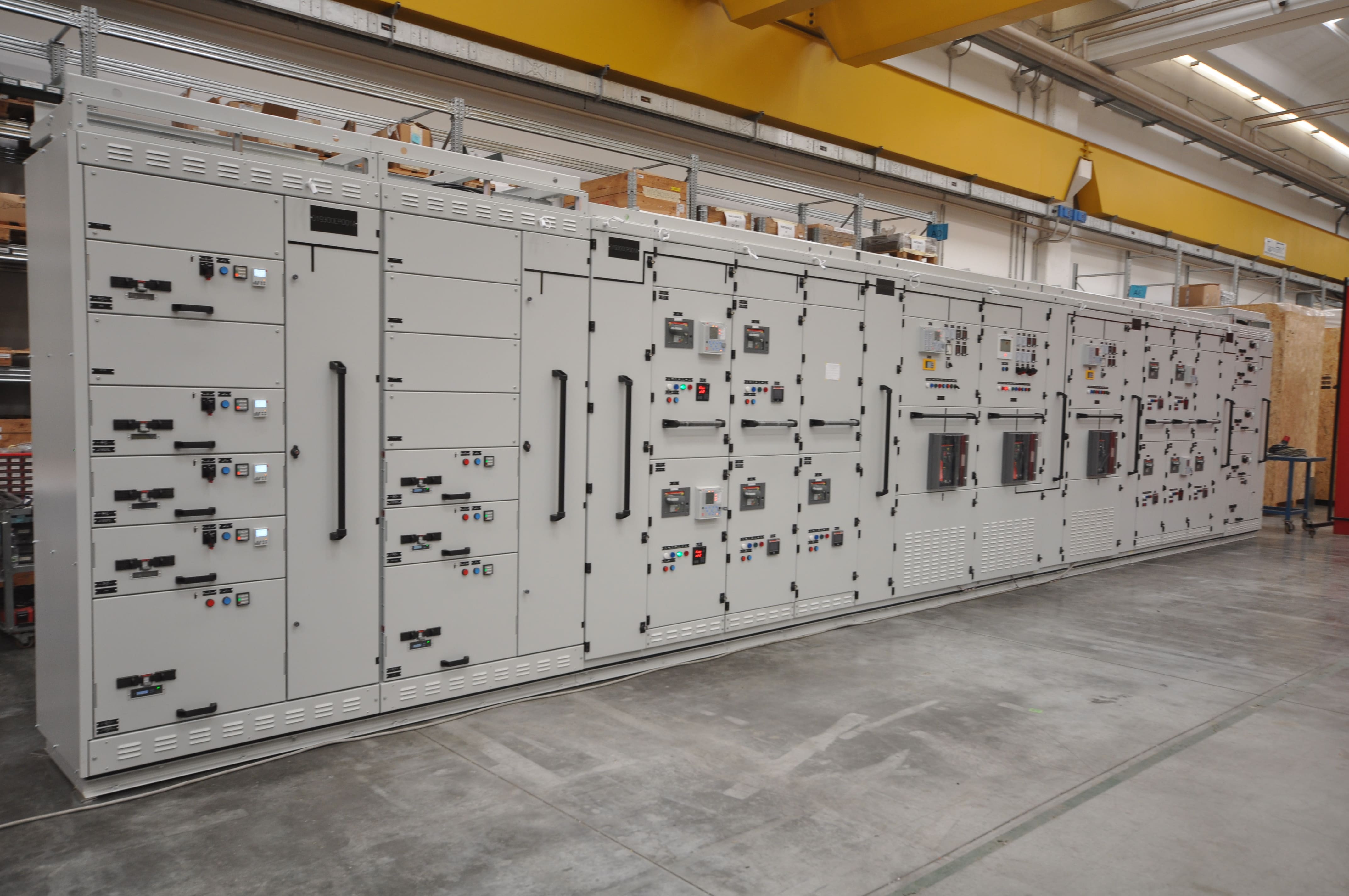

A low-voltage switchboard complies with IEC 61439 when it meets the applicable requirements for the complete assembly, its design has been verified, and every manufactured unit undergoes the required routine verification.
Using circuit breakers, busbars and other components that comply with their respective standards is not enough. In addition it is also necessary to verify how these elements work together within the switchboard under the conditions for which it was designed.
For anyone selecting a low-voltage (LV) switchboard, the question to ask the supplier is therefore a practical one: what verification evidence demonstrates that the proposed configuration is suitable for the required performance?
IEC 61439-1 and IEC 61439-2: what is the difference?
For Low-Voltage power Switchgear and controlgear assemblies, such as Power Centers and Motor Control Centers, IEC 61439-1 and IEC 61439-2 apply together.
IEC 61439-1 establishes the general rules. It defines construction requirements and verification procedures covering aspects such as electrical insulation, protection against electric shock, resistance to electrodynamic forces, and temperature rise during operation.
IEC 61439-2 adds the specific requirements for power switchgear and controlgear assemblies used for power distribution and for supplying or controlling electrical loads. It covers assemblies with rated voltages up to 1,000 V AC or 1,500 V DC.
The two parts are complementary. For a power assembly, referring to IEC 61439-1 alone does not identify all the applicable requirements. Other types of assemblies may require a different part of the series, to be used alongside the general rules.
Why is component compliance not enough?
An electrical switchboard must be assessed as a complete assembly, because the arrangement of devices, connections, enclosure and ventilation all influence its behaviour and performance.
For example, a circuit breaker suitable for a given current does not, by itself, demonstrate that the switchboard can operate at that current under the specified conditions. The heat generated by the other components and the assembly’s ability to dissipate it must also be taken into account.
The same applies to short-circuit conditions: a circuit breaker’s breaking capacity and the short-circuit withstand capability of the switchboard are different characteristics. The former concerns the device’s ability to interrupt a fault; the latter concerns the assembly’s response to the specified stresses and its ability to withstand them.
IEC 61439 compliance therefore applies to the complete assembly and the configuration actually manufactured.
What verifications does IEC 61439 require?
The standard distinguishes between design verification, type testing of prototypes, and routine verification. Each addresses different questions.
Design verification demonstrates that the design is suitable
Design verification is intended to demonstrate that the constructional solution meets the applicable requirements.
It covers, among other aspects:
- The strength and suitability of the selected materials and components;
- Temperature rise within the switchboard during operation;
- Short-circuit withstand capability;
- Insulation properties;
- Clearances and creepage distances;
- Protection against electric shock;
- The degree of protection provided by the enclosure;
- Mechanical operation.
The standard permits different verification methods according to the requirement, including testing, comparison with a verified reference design, and assessments, including calculations. Each method has specific conditions and limitations: it cannot be selected freely for every type of verification.
Routine verification applies to every manufactured switchboard
Routine verification checks that each individual switchboard has been correctly manufactured and helps identify potential material or assembly defects.
Depending on the applicable requirements, it includes checks on the enclosure, connections, power and protective circuits, wiring, insulation and operation.
The distinction is straightforward: design verification concerns the constructional solution, while routine verification concerns the individual assembly manufactured at the factory and delivered to the customer. Final testing of an individual switchboard does not replace design verification.
Who is responsible for compliance?
IEC 61439 distinguishes between the original manufacturer, who develops the design and carries out the relevant verifications, and the assembly manufacturer, who assumes responsibility for the completed assembly. So the two roles may be performed by the same company.
When the assembly manufacturer uses a system that has already been verified, it must follow the instructions and conditions defined for that system by the original manufacturer.
If it introduces modifications that are not covered by those instructions, it must assess their effects and carry out the necessary verifications on the affected aspects. For such modifications, it assumes the role of the original manufacturer.
This becomes particularly important when custom variations are requested. Replacing a device, modifying the busbars or changing the ventilation can affect performance. It is therefore necessary to establish that the revised configuration remains covered by the available verification evidence.
What information is needed to choose a compliant LV Switchboard suitable for the installation?
Compliance with the standard and suitability for the intended application must be assessed together, for this reason a switchboard should be selected by considering both the electrical parameters and the conditions at the installation site, including the physical layout and environmental characteristics such as temperature, humidity and pollution degree.
The technical specification should include:
- Operating voltage, insulation level, frequency and required currents;
- Short-circuit conditions at the installation point;
- Connected loads and their simultaneity of operation;
- Ambient temperature, altitude, and the presence of dust or moisture;
- Required degree of protection;
- Access, maintenance and expansion requirements;
- Delivery and transportation arrangements for the switchboard sections to the installation site.
For example, allowing spare space for future outgoing feeders is useful, but it does not demonstrate that any expansion will be possible. Additional loads may change the overall load and the thermal behaviour of the switchboard. Therefore expansion capabilities should be defined during the design stage.
What documents should you request from the supplier?
When evaluating a supply, it is useful to agree on documentation that links the delivered switchboard to its characteristics and the relevant verification evidence.
The documentation to consider includes:
- Switchboard identification and rated data;
- Applicable standards and their respective editions;
- Updated drawings and diagrams of the supplied configuration;
- Evidence of the applicable design verifications;
- Records of routine verifications;
- Installation, operation and maintenance instructions;
- Compliance documents required for the supply.
The content and delivery arrangements should be agreed upon when placing the order. Thus, a generic statement such as “IEC 61439-certified switchboard” requires further clarification: which configuration does it refer to, and which performance characteristics does it document?
Frequently Asked Questions about IEC 61439
Is IEC 61439-1 sufficient for a power switchboard?
No. For power switchgear and controlgear assemblies, IEC 61439-1 must be applied together with IEC 61439-2, which contains the specific product requirements.
Do all switchboards have to undergo design tests again?
It is not necessary to repeat all tests on every individual unit. Design verification can cover permitted configurations within the specified conditions. However, every manufactured switchboard must undergo routine verification.
Does a modified switchboard retain its original compliance status?
The modification must be assessed. If the revised configuration is not covered by the existing verification evidence, the affected aspects must be verified and the documentation updated.
Specify Your LV Switchboard with IMESA
Selecting an LV switchboard starts with understanding the installation, in fact network data, loads, environmental conditions and operating requirements provide the basis for defining the required performance.
Discover the range of IMESA low-voltage switchboards and share your project specifications to identify the appropriate configuration and the documentation required for the supply.