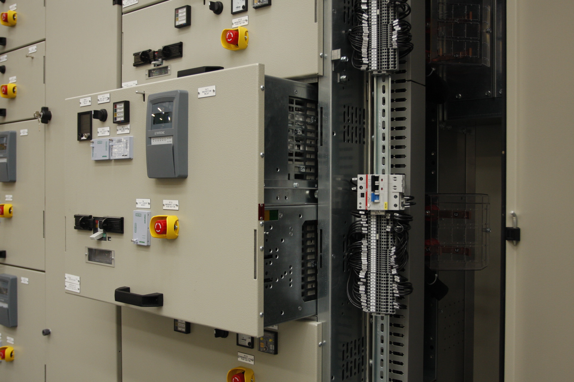

The forms of separation defined by IEC 61439-2 specify how the interior of a switchboard is further compartmentalized, using barriers and partitions, between the busbar compartment, functional units, and connection terminals for outgoing field cables.
These levels of internal compartmentalization are classified from Form 1 (the lowest level, with no internal separation) to Form 4b (where separate compartments are provided for each area).
In a Motor Control Center (MCC), the form of separation is combined with the type of drawer: fixed or withdrawable. The integration of these two configurations determines whether maintenance can be carried out on an individual motor feeder without shutting down the other units.
For a process plant, the difference is significant. With one configuration, a drawer can be replaced in just a few minutes and, depending on the construction form adopted, work can be carried out on an individual motor feeder independently of the operation of the others. With the other configuration, an entire production line must be shut down for the duration of the maintenance work.
What is a Motor Control Center?
A Motor Control Center (MCC) is a low-voltage electrical switchboard that houses the motor feeders of an industrial plant in a single assembly. Each feeder is a functional unit comprising a protective device, contactor, thermal or electronic overload protection, and auxiliary circuits.
MCCs supply power to pumps, fans, compressors, conveyor belts, and mixers. They are commonly found in cement plants, paper mills, petrochemical and metallurgical plants, power stations, and water treatment facilities. Like other low-voltage power switchboards, they are designed and verified in accordance with IEC 61439-1 and IEC 61439-2.
What is the purpose of the forms of separation?
IEC 61439-2 identifies two main purposes for internal separation:
- Protection against contact with hazardous live parts belonging to adjacent functional units.
- Protection against the passage of solid foreign objects from one unit to another.
In practical terms, the form of separation determines which parts remain accessible when the door of a functional unit is opened. A higher level of separation also helps limit the spread of a fault to adjacent units.
What forms of separation are specified by IEC 61439-2?
The standard distinguishes between three main elements: the distribution busbars, functional units, and terminals for external conductors. The forms of separation describe which of these elements are separated from one another.
| Form | Busbars separated from the functional units | Functional units separated from one another | Terminals separated from the busbars | Terminal position |
|---|---|---|---|---|
| 1 | No | No | No | No internal separation |
| 2a | Yes | No | No | Common compartment with the busbars |
| 2b | Yes | No | Yes | Common compartment with the functional units |
| 3a | Yes | Yes | No | Common compartment with the busbars |
| 3b | Yes | Yes | Yes | Common compartment, separated from the busbars and functional units |
| 4a | Yes | Yes | Yes | In the same compartment as its own functional unit |
| 4b | Yes | Yes | Yes | In a dedicated compartment for each outgoing feeder, separate from its functional unit |
The choice between Forms 4a and 4b mainly depends on how the cables are managed. With Form 4b, work can be carried out on the terminals of a feeder without opening the equipment compartment, and vice versa.
The required form of separation, in its full designation, must be specified in the technical specifications and verified against the design. For example, specifying “Form 4” without the additional letter leaves room for interpretation precisely on the point that has the greatest impact on maintenance.
What is the difference between fixed and withdrawable drawers?
The form of separation tells us how the switchboard is internally divided. The type of construction (fixed or withdrawable) defines how the functional unit is connected to the main and auxiliary circuits, and how it can be accessed for repair or replacement.
- Fixed drawer. It is permanently installed and connected. To replace the equipment installed inside it, the relevant conductors must be disconnected and the mechanical fixing screws securing the components must be removed. It may be necessary to de-energize the switchboard’s main busbars.
- Withdrawable drawer. It can be removed from the switchboard and returned to service even while the main busbars remain energized. It remains mechanically attached to the switchboard and moves along guide rails between defined positions: fully connected, test, and fully withdrawn (it may also occupy intermediate positions).
A withdrawable drawer typically has four positions:
- Connected: main and auxiliary circuits are connected; the feeder is in service.
- Test: main circuits are disconnected, while auxiliary circuits remain connected. Control logic and signalling can be tested without supplying power to the motor.
- Isolated: both main and auxiliary circuits are disconnected, with guaranteed isolation distances for both power circuits and control and monitoring circuits.
- Withdrawn: the drawer is completely removed from the switchboard and can be replaced with a spare unit.
IEC 61439-2 also provides a three-letter code to identify the type of connection for the unit: incoming main circuit, outgoing main circuit, and auxiliary circuits. F stands for fixed connection, D for disconnectable connection, and W for withdrawable connection. A fully withdrawable unit is therefore designated WWW, while a fixed unit is designated FFF.
How do service continuity and maintenance change?
The form of separation and the type of drawer must be considered together. A high level of separation combined with fixed drawers provides greater operator protection, but does not significantly reduce replacement times. Withdrawable drawers in a switchboard with a low level of separation reduce maintenance times, but limit the work that can be carried out while adjacent units remain in service.
| Configuration | Maintenance work on an individual feeder | Impact on the rest of the plant |
|---|---|---|
| Form 2b, fixed units | Switchboard or section shutdown | Extended shutdown, long downtime |
| Form 3b, fixed units | Maintenance work on an individual unit using dedicated procedures | Limited downtime, slow replacement |
| Form 4b, withdrawable units | Drawer withdrawal and replacement | Other feeders remain in service |
With standardized withdrawable drawers, it is advisable to keep a number of spare units in stock for each size. Replacement then becomes a matter of minutes, while the faulty drawer can be repaired in the electrical workshop.
One point remains essential: all work on energized switchboards or in the vicinity of live parts must be carried out in accordance with the procedures set out in CEI EN 50110-1 and CEI 11-27. Internal separation reduces risks, but it does not replace proper electrical work safety procedures.
What interlocks are required in an MCC with withdrawable drawers?
Interlocks prevent operations from being carried out in the wrong sequence. The most common ones include:
- The drawer can only be inserted or withdrawn when the circuit breaker is open (the operation must take place with no current flowing).
- The door cannot be opened while the unit is connected and in service.
- Provision for locking the drawer in the isolated position during maintenance operations.
- Shutters that cover the fixed contacts when the drawer is withdrawn.
- Indication of the drawer position to the control system.
Does the form of separation guarantee internal arc protection?
No. The form of separation addresses protection against direct contact (electric shock hazards) and the possible transfer of foreign objects from one compartment to another. The behaviour of low-voltage switchboards in the event of an internal arc is assessed through specific tests in accordance with the technical report IEC TR 61641.
These two requirements are complementary and must be specified separately. A Form 4b switchboard is not necessarily an internal arc-tested switchboard.
How to choose the right MCC configuration?
The selection process starts with four key questions: What is the cost of one hour of production downtime? How many motor feeders are there? Who is responsible for maintenance? How much space is available in the electrical switchroom?
Within the IMESA product range, the two solutions address different requirements:
| Feature | MCC32 | MCCF |
|---|---|---|
| Unit configuration | Withdrawable units | Fixed units |
| Rated voltage | Up to 690 V | Up to 690 V |
| Rated busbar current | Up to 3,750 A | Up to 1,600 A |
| Short-time withstand current (1 s) | Up to 80 kA | Up to 50 kA |
| Forms of separation | 3b, 4a, 4b | 2b, 3b, 4a, 4b |
| Degree of protection with doors closed | IP54 | Up to IP55 |
The MCC32 is recommended when service continuity is a priority, as in continuous-process plants. The MCCF is suitable for plants with fewer motor feeders or scheduled maintenance windows. For incoming feeders and large power distribution feeders, combined configurations integrating MCC switchboards with Power Center (PC) switchboards can also be implemented, with ratings of up to 6,300 A.
MCCs can also exchange status information, measurements and alarms from individual feeders with the SCADA automation and supervision system. Typical applications are described on the dedicated Industry sector page.
Frequently asked questions about forms of separation and withdrawable units in MCCs
What is the difference between Form 4a and Form 4b?
In both configurations, the busbars, functional units and terminals are separated. In Form 4a, the terminals are located in the same compartment as their associated functional unit (e.g. the circuit breaker, motor starter, etc.). In Form 4b, the terminals are housed in a separate compartment, which can be accessed without having to open the equipment compartment.
Does a withdrawable unit allow work to be carried out while the switchboard is energized?
It allows an individual feeder to be withdrawn and replaced while the other feeders remain energized. However, all operating procedures must still comply with the applicable electrical safety requirements.
What is the purpose of the test position?
It allows the correct operation of controls, interlocks and signalling devices to be checked, with the auxiliary circuits energized and the main circuits disconnected. In this drawer position, the motor starter can be activated, but the motor itself is not supplied with power.
Can an MCC with fixed drawers be converted into one with withdrawable drawers?
This type of conversion is not foreseen. The structure, connections and separation arrangements are different, and any modifications required would invalidate the certifications obtained through the design verification tests specified by the applicable product standards (IEC 61439-1 / 2). We discuss this topic in our article on when a low-voltage switchboard is truly compliant with IEC 61439.
Configure your MCC with IMESA
The number of feeders, motor power ratings, control logic and maintenance strategy determine the most suitable form of separation and drawer type. Share your plant specifications with our technical department via the Contact page: we will help you define the right Motor Control Center configuration.